
Front End & Breakout Board for sSDR and dSDR
A modular PCIe x4 adapter platform with integrated RF front-end options for synchronized multi-channel SDR systems.
The Wavelet Lab Front End board is designed for sSDR and dSDR modules, adding synchronized RF connectivity, fast TX/RX switching, external SMA access, clock synchronization, and software-controllable RF path configuration for advanced MIMO, TDD, beamforming, and direction-finding applications.
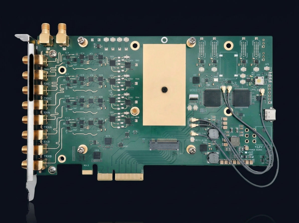
Why FE-Board
The Front End (FE) is a modular high-performance adapter board for Wavelet Lab sSDR and dSDR modules. It provides up to 4 RX and 4 TX RF paths, synchronized operation, fast TX/RX switching for TDD applications, and integrated RF front-end components including low-noise amplifiers, power amplifiers, filters, and switches. The board is intended for users building multi-channel SDR systems where RF routing, external antenna access, synchronization, and repeatable lab or field integration are required. A lighter Breakout Board version is also available for users who want the same module-carrier concept without integrated RF front-end components. This version is better suited for custom RF front-end development, lab integration, and users who want to connect their own RF chains.
Key capabilities
Modular carrier for sSDR and dSDR
M.2 Key M socket integrates Wavelet Lab SDR modules into a PCIe x4 host form factor.
Integrated RF front-end
Up to 4 RX / 4 TX synchronized RF paths with LNAs, PAs, filters, and switches from 50 MHz to 7.2 GHz.
Fast TX/RX switching
Sub-microsecond TX/RX switching enables TDD operation for cellular and time-division workflows.
Synchronization & timing
REFCLK and SYSREF domains with on-board oscillator and optional GPS synchronization for coherent operation.
System architecture
The Front End board carries an sSDR or dSDR module via an M.2 Key M socket and exposes synchronized RF paths to eight SMA connectors on the PCI bracket. Integrated LNAs, PAs, switched filter banks, attenuators, and TX/RX switches form a software-controllable RF chain with REFCLK / SYSREF synchronization, an on-board oscillator, and an optional GPS reference.
sSDR and dSDR module support
The Front End board accepts both sSDR and dSDR modules in its M.2 Key M socket and exposes their RX/TX paths through synchronized RF distribution.
| Module | RFIC | Channels | Sample Rate | Channel Bandwidth |
|---|---|---|---|---|
| sSDR | LMS7002M + LMS8001 | 2 RX / 2 TX | 4–100 MSps | 0.5–90 MHz |
| dSDR | AFE7900 / AFE7901 / AFE7950 | 6 RX / 4 TX | 0.1–500 MSps | 0.5–500 MHz |
With sSDR, the first two RX/TX RF pairs are used. With dSDR, the board supports four RX and four TX RF distribution paths.
Integrated RF front-end from 50 MHz to 7.2 GHz
The Front End board includes RF components for filtering, amplification, switching, and software-controlled path selection. Users can switch filter banks, set attenuators, select antenna paths, enable or disable RX/TX channels, and configure loopback paths for calibration.
| Filter Bank | Frequency Range |
|---|---|
| Filter 1 | 50–1000 MHz |
| Filter 2 | 1000–2000 MHz |
| Filter 3 | 2000–3500 MHz |
| Filter 4 | 2500–5000 MHz |
| Filter 5 | 3500–7100 MHz |
Flexible RF configurations
Operate the board as a unified 4×4 MIMO system or split it into two independent 2×2 MIMO subsystems.
4×4 MIMO System
Use the board as a synchronized 4 RX / 4 TX RF system for MIMO, beamforming, direction finding, and multi-channel RF capture.
Two Independent 2×2 MIMO Systems
Use the board as two separate 2×2 MIMO systems for test setups, multi-radio experiments, or applications where independent RF chains are required.
Breakout Board
A simplified version of the FE board without the integrated RF front-end components.
Use the Breakout Board when you need:
- Custom RF front-end design
- Direct lab access to SDR module signals
- External LNAs, PAs, filters, or switches
- Custom antenna routing
- Prototype integration with dSDR or sSDR
- Lower-cost carrier functionality
Software & Platform Ecosystem
Applications & Use Cases
Cellular communication
4G/5G wireless systems, MIMO, and TDD workflows with compatibility for Amarisoft and srsRAN.
Direction finding
Multi-channel synchronized receive paths for direction-of-arrival and transmitter-localization workflows.
Beamforming
Multi-channel RF systems for directional transmit and receive processing, improved range, and interference rejection.
Lab and RF integration
Breakout-board workflows for custom RF front ends, direct signal access, and prototype validation.
Technical specifications
| Compatible modules | sSDR, dSDR |
| Module socket | M.2 Key M |
| Host form factor | PCIe x4 |
| RF paths | Up to 4 RX / 4 TX |
| RF front-end range | 50 MHz – 7.2 GHz |
| External RF connectors | 8 SMA on PCI bracket |
| Module-side RF connectors | MHF7 |
| Synchronization | REFCLK · SYSREF · GPS option |
| Switching | Fast TX/RX switching for TDD |
| Software control | Filters · attenuators · antenna paths · channel enable |
| Calibration | TX/RX loopback mode |
| Breakout option | Available without integrated RF front-end |
Part of the Unified Wavelet SDR Platform
Choose the right form factor for your mission.
| Spec | uSDR | xSDR | sSDR | dSDR |
|---|---|---|---|---|
| Frequency Range | 70 MHz – 3.8 GHz | 30 MHz – 3.8 GHz | 30 MHz – 11 GHz | Up to 12 GHz (model-dependent) |
| Channels | 2×2 | 2 RX / 2 TX | 2 RX / 2 TX | Up to 6 RX / 4 TX |
| Bandwidth | 56 MHz | Up to 90 MHz | 0.5 – 120 MHz | up to 1 GHz |
| Interface | M.2 2230 A+E key · USB 2.0 · PCIe 2.0 ×2 | M.2 2230 A+E key · USB 2.0 · PCIe 2.0 ×2 | M.2 2242 M-Key · PCIe 3.0 ×4 · USB 2.0 | M.2 3080 M-Key · PCIe 4.0 ×4 |
| Form factor | M.2 2230 | M.2 2230 | M.2 2242 | M.2 3080 |
| Sync | 10 MHz / PPS | External clock | TCXO / ext | External clock |
Build synchronized multi-channel SDR systems
Use the Front End or Breakout Board with sSDR and dSDR modules for MIMO, TDD, beamforming, direction finding, and custom RF integration.